The Working Principle and Common Failure Analysis of the Air Compressor System of Medical Oxygen Generator
2024-04-03
Oxygen plays an indispensable role in hospital rescue, anesthesia, surgery, and treatment, and has an extremely important role in medical rescue. At present, hospitals mainly have three types of oxygen supply methods, namely, liquid oxygen supply, oxygen cylinder supply and molecular Medical Oxygen Generator supply. Among them, molecular sieve oxygen concentrator has become the main oxygen source used in hospitals with its advantages of modular structure, high degree of automation and easy operation.
The normal operation of medical oxygen generator is a necessary condition for the normal development of clinical work in hospitals. In the process of oxygen production, the air passes successively through five modules (air compressor, air storage tank, cold dryer, oxygen generation system and oxygen storage tank), and then form medical oxygen. The air compressor system provides oxygen, the required compressed air is at the forefront of the entire oxygen generation unit, which has a very important role. Therefore, it is necessary to understand the working principle of the air compressor system and analyze its common faults.
1. The workflow and principle of the air compressor system
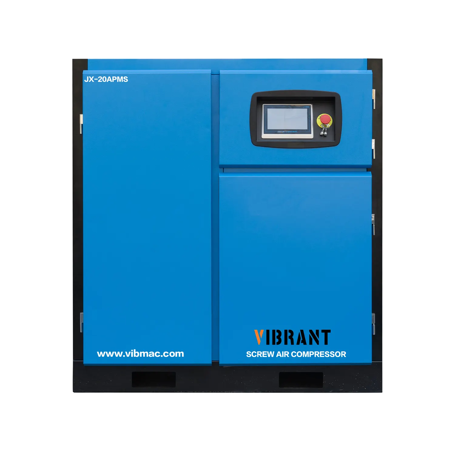
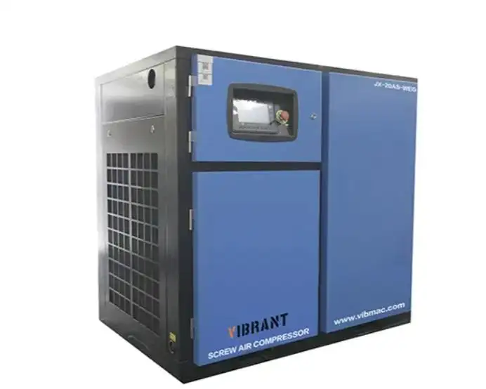
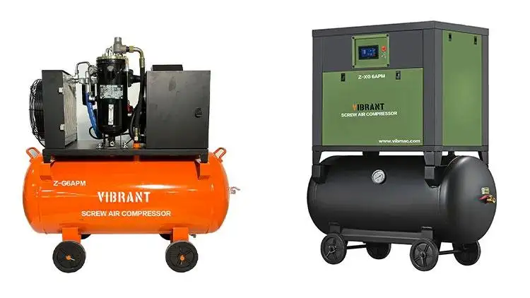
The main function of the air compressor system is to pressurize the ambient air to the pressure required by the molecular sieve adsorbed at the inlet of the tower to ensure the normal operation of the molecular sieve. Compared with piston air compressor, screw air compressor has the advantages of strong reliability, simple operation and maintenance, good power balance and adaptability, etc. It is suitable for long time operation, which is in line with the nature of 24h work in hospitals. Therefore, the screw air compressor is generally used in the oxygen generating unit. Our company will take the screw air compressor used in the oxygen generating unit of a hospital as an example to explain the workflow and principle of the air compressor system.
1.1 Workflow
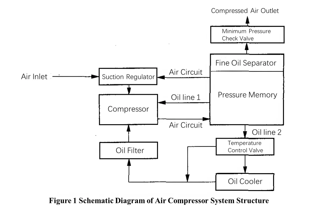
The air compressor system consists of four parts: suction regulator, compressor, pressure storage, and piping (oil and gas lines). The structure of the air compressor system is schematically shown in Figure 1.
The air is fed into the compressor through the control of suction regulator, the compressor adopts coupling drive and is rotated by three-phase motor for air compression, and the compressed air is sent to the pressure memory through the air circuit, the oil is returned to the compressor chamber through the oil cooler and the oil filter to play the role of lubrication and cooling, and the compressed air passes through the fine oil separator to filter out the oil, and finally enters into the air storage tank through the minimum pressure check valve.
1.2 Principle of operation
During the oxygen production process, the compressor is made to work in continuous mode through the microcontroller, with 2 operating states: loaded operation and no-load operation. Two pressure points are set on the microcontroller, the upper limit is 0.74MPa and the lower limit is 0.34MPa, and the generated air pressure is transmitted to the microcontroller through the sensor.
1.2.1 Loading operational status
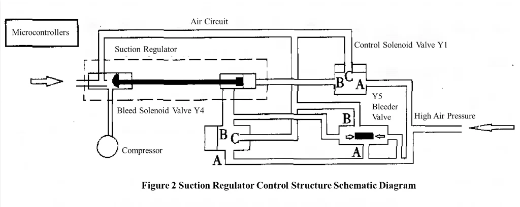
In the loading operation state (shown in Figure 2), the microcontroller provides 24V DC power to the solenoid valve Y1 and solenoid valve Y4 of the suction regulator. The spool of the solenoid valve Y1 moves downward, the B air path and the C air path are connected, and the A air path is closed, thus forming a low air pressure space, solenoid valve Y4 spool move upward, A airway and B airway are connected, C airway is closed, forming a high air pressure space; bleeder valve Y5 due to the left side of the role of high air pressure, the valve spool moves to the right, close the A-B airway, that is, close the bleeder airway; in the common effects of the three valves, the suction regulator linkage makes the movement to the end of the right, the inlet port is completely open, and a large amount of air enters. Pressure continues to rise, reaching the upper limit value of 0.74MPa, the micro-controller control compressor turns to no-load operation state.
1.2.2 No-load operation status
In the no-load operation state (shown in Figure 2), the microcontroller stops supplying power to the solenoid valve Y1 and solenoid valve Y4 of the suction regulator. The solenoid valve Y1 spool releases the upward action, the A gas path and the B gas path are connected, and the C gas path is closed, forming a high air pressure space, which is sent to the suction regulator; solenoid valve Y4 spool release downward action, B airway and C airway are connected, A airway is closed, forming a low-pressure space; bleeder valve Y5 due to the effect of the high-pressure on the right side , the valve spool moves to the left, the A airway and the B airway are connected to bleed air. The combined action of the 3 valves causes the suction regulator linkage to move to the left, completely closing the air inlet, preventing air from entering and no compressed air being produced. At this time, the high air pressure of the pressure memory is discharged from the air inlet through the bleeder valve Y5, and it reaches the upper limit value of 0.74MPa and starts to fall, when the pressure falls to the lower limit value of 0.34MPa, the micro-controller is transferred to the loading operation state, and after that, it is the non-stop alternating operation state.
1.2.3 Minimum pressure check valves
The function of the minimum pressure check valve is to isolate the internal and external pressure, and the pressure difference is 0.03MPa. In the loading operation state, when the internal pressure (pressure reservoir pressure) is higher than the external pressure of 0.03MPa, the check valve is opened, and the compressed air is delivered out. In the unloaded operation state, the internal pressure starts to fall from the upper limit value, and the check valve is closed when the pressure difference is lower than 0.03MPa because of the fast falling speed.
1.2.4 Temperature control valves: Medical Oxygen Generator
The temperature control valve is set on the oil circuit 2, its function is to cool the oil to ensure the normal operation of the compressor. When the temperature of the oil circuit rises to 70℃, the temperature control valve operates, and the oil returns to the compressor chamber through the oil cooler; when the temperature of the oil circuit is below 70℃, the temperature control valve does not operate, and the oil returns to the chamber directly without cooling. In the case of oil cooling, the compressor temperature is controlled at about 84℃, if the temperature is too high, it will cause machine downtime or even damage.
2. Common fault disposal and maintenance: Medical Oxygen Generator
2.1 Fault No.1
2.1.1 Fault phenomenon
The pressure value of the air compressor system did not rise to the upper limit value of 0.74MPa, and it has been in the loading working condition, and the air tank pressure is low.
2.1.2 Failure analysis
First, check the oxygen concentrator. It is found that the oxygen concentration and oxygen output are good, and there is no problem with the function of the oxygen concentrator. Turn off the oxygen generator, there is no fault phenomenon, the air tank pressure also rises, it can be seen that the compressed air is not enough to meet the demand, so it can be ruled out the oxygen generator failure. Secondly, replace the compressor air inlet air filter, it is found that the failure phenomenon still exists, we can rule out the filter failure. Finally, it can be determined that the problem is caused by the lack of air supply from the compressor itself, and the suction regulator has a lot to do with it. Through the offline inspection program, we found that the suction regulator air inlet is not completely open, the action of the solenoid valve Y1 downwards is not complete, failed to completely close the A airway, so that the suction regulator valve linkage can not move to the right to the end, after the cleaning process of the solenoid valve Y1, the fault is eliminated.
2.1.3 Offline inspection program
It is very unsafe to check the operating status of the suction regulator while the compressor is in operation, so we propose an offline inspection program. As can be seen from Figure 3, an air storage tank replaces the pressure memory to provide high air pressure, and a 24V DC power supply replaces the microcontroller to supply power manually. With this scheme, it is easier and safer to check the cause of failure of the suction regulator.

2.2 Fault No.2
2.2.1 Fault phenomenon
Air compressor temperature is too high, over 90℃.
2.2.2 Failure analysis
In the case of ensuring the normal operation of indoor air conditioning, check whether the air compressor system has oil leakage phenomenon, whether the oil circuit is intact. If the oil pipe is ruptured, replace it in time: if the oil circuit is normal, check the oil filter and oil cooler, and finally find that the oil cooler is too dirty, after cleaning the trouble is solved. In addition, in summer, we recommend that you open the door on one side of the compressor, which has been proved by experiments to reduce the temperature of the compressor by 4℃, and it helps to prolong the service life of the oil pipe.
2.3 Fault No.3
2.3.1 Fault phenomenon
In the loading state of the compressor, it can be loaded to the upper limit value of 0.74MPa, but there is a bleeding phenomenon.
2.3.2 Failure analysis
According to the offline inspection program, it was found that there is a bleeder phenomenon, check the electromagnetic Y1, Y4 and bleeder valve Y5, we found that the bleeder valve Y5 is discharging, and carefully check the bleeder valve, we found that the internal sealing ring is damaged. After replacing the sealing ring, the problem is solved. This failure does not affect the normal operation of the compressor, but it will cause the loading time too long, increasing the overall loss of the air pressure system.
2.4 Maintenance: Medical Oxygen Generator
Doing a good job of regular maintenance can reduce the incidence of equipment failure, ensuring that the effective operation of the equipment time and extending the service life of the equipment, reducing maintenance costs, saving money for the hospital.
The daily maintenance of the air compressor system mainly includes 4 points: (1) regular replace the air and oil filters; (2) check the conditions of the cold and damage to the air and pipeline, there are problems in a timely manner to deal with or replace: (3) clean regularly for those which are easy to material and mechanical fatigue of the solenoid valve components; (4) pay attention to the observation of the machine running anomalies, and timely solve any problems.
3. Conclusion
The compressor system is at the forefront of the medical oxygen generator unit, understanding the working principle of the system and the failure phenomenon is the premise of the normal work of the medical oxygen generator. Our company introduces in detail the workflow and working principle of medical oxygen generator and air compressor system, analyzes the common faults of air compressor system, and puts forward the offline inspection plan of air regulator, which is of great help to its future troubleshooting and repair, and puts forward the requirements for the routine maintenance of air compressor system. Read new blog here.


