Study on the Emulsification of Air Compressor Lubricant in Subway Vehicles
2024-03-14
Emulsification of air compressor lubricant appeared frequently in a city subway, and the operation rate of air compressors could not reach the minimum operation rate requirement. And when the air compressor is not running at an adequate rate, the lubricating oil may emulsify, and a heavily emulsified lubricating oil will not lubricate the compressor rotor and bearings as expected. It leads to the failure of air compressor such as load increase, rotor jamming, abnormal sound, etc., which may cause the compressor to be scrapped in serious cases, or even occur major accidents. In order to avoid repeated replacement of lubricating oil and affect the normal operation of the equipment, our company has put forward a rectification plan for the operation rate of the air compressor.
1. Equipment Description
The air source module of a city subway uses a PM VSD screw air compressor set and a LTZ015.0H type double-tower dryer, and the lubricant used in the air compressor is ANDEROL 3057M. Each A-vehicle is equipped with a set of air source module, and the compressed air is cooled and filtered by the air source module and sent to the air-using equipment.
For intermittent operation conditions, the duty cycle of the compressor unit (operating rate ED) should be higher than 30%. The formula for calculating the operating rate is as follows: ED = tc/tv * 100% (in the formula, tc means compressor operating time and tv means vehicle operating time).
2. Analysis of the Causes: Air Compressor Lubricant
2.1 Reasons for Emulsification of Lubricating Oil
The air contains a certain amount of water vapor, when the water vapor content in the compressed air exceeds its water-containing capacity, the water vapor will liquefy into liquid water, and the liquid water is mixed with the lubricant and forms an emulsion. Under high temperature and high humidity conditions, especially if the compressor unit does not reach the minimum operating rate, the lubricant is susceptible to emulsification. The main mechanism is that, due to the characteristics of the use of subways and vehicles, especially on newly opened lines, there are a variety of working conditions, such as storage, testing, trial operation, commissioning, unloaded operation, non-routine operation on the main line (with far fewer passengers than planned) and regular operation on the main line.
And the compressor of the braking system has a large start-up interval, short working time, and slow rise in temperature, resulting in a low operating temperature of the compressor oil. In addition, the installation and operation on the locomotive can not guarantee the same frequency of several hours of point inspection and drainage, and there is a high probability that the emulsification of lubricating oil in the air compressor will occur. Under such an air compression system, if its system temperature at a certain pressure is lower than or equal to the dew point temperature at this pressure, the gaseous water in the compressed air will liquefy to form liquid water, which will mix with the lubricating oil in the compressor, thus causing lubricating oil emulsification.
2.2 Pressure Dew Point
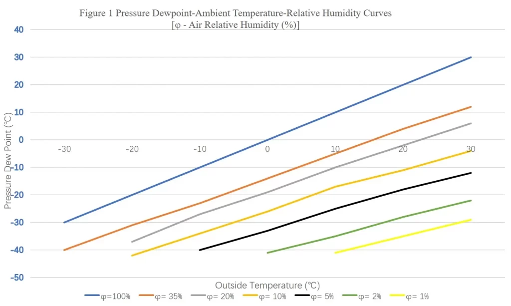
Pressure dew point : When unsaturated wet air is compressed, the density of water vapor increases and the temperature rises, and when the compressed air is cooled, the relative humidity increases. When the temperature continues to fall and the relative humidity reaches 100%, there will be droplets of water from the compressed air precipitation, and this time the temperature is the “pressure dew point” of compressed air. The “pressure dew point” is not only related to relative humidity and temperature, but also to pressure. Therefore, the dew point temperature of compressed air in a compressor system varies in real time with changes in ambient temperature, air humidity, and system pressure.
2.3 Emulsification Phenomeon
Emulsion is a mixture of oil and water, when the water content reaches about 0.15% (1500 ppm) , the lubricant will be visibly cloudy, which is called mild emulsification, which can be removed by beating the wind for 30 minutes or longer. If mild emulsification is not removed in time, emulsification will worsen. When the water content in the lubricant is high it is said to be moderately or severely emulsified and it is necessary to change the oil and inspect the equipment. The water content reaches about 3% (30,000 ppm), at which point the compressor is cold and the water starts to separate from the oil.
Lubricating oil in the operation of the air compressor bears the important function of sealing, lubrication, cooling, and at the same time has the role of noise reduction, vibration damping and part of the power transmission, and its importance is equivalent to the blood of the air compressor. In order to prevent emulsification of lubricating oil, for screw compressors normally put into use in vehicles, it is required that their operating rate should be at least 30%; for screw compressors that are not put into use in vehicles, it is necessary to ensure that the duration of a single blow is greater than or equal to 30 minutes. At the same time, the factory should regularly update the filter elements of oil and air filters, and ensure that no impurities can accidentally enter the lubricating oil system of the air compressor during the refueling and oil change process.
3. Prevention and Control Program for Lubricant Emulsification
In order to avoid emulsification of the compressor lubricant, we have to make sure that the temperature inside the compressor pressure system is always higher than the dew point temperature at that pressure. Therefore, we can realize this requirement by improving the running rate of the air compressor or prolonging the duration of the air compressor’s single beating time.On the premise that we properly maintain and service the air supply unit, there are ways to prevent lubricant emulsification:
- (1) Increase additional air use in the air system
Increase the actual air used by the vehicle (air for air springs, air for brakes, etc.). For example, every day after returning to the warehouse you need to slightly open the main air cylinder valve, start the air compressor to work continuously for about 30 minutes, which is suitable for temporary improvement in mild emulsification of lubricating oil.
- (2)Install an idling device
Install the air source unit and the air compressor in the idling unit, and after the air compressor enters the idling mode, the pressure of the air compressor system is maintained at about 400kPa. At this time instead of transporting compressed air to the downstream pipelines and equipment of the compressor, there is an internal cycle within the compressor system, and the amount of air compressed is not much, the heat generated in the compression process is also very small. If the air compressor is switched to the idling mode within a relatively short period of time after startup, the temperature in the air compressor system is much lower than during normal loading operation. However, there is no data available to show that this temperature is necessarily higher than the pressure dew point temperature under extreme conditions (high temperatures and high humidity), which would also indicate that there would be a risk of lubricant emulsification.
If you wait until the compressor system temperature reaches a relatively high value after the compressor has been started for a long period of time, then you can switch the compressor to the idling operation mode. As the air compressor is still in a state of continuous operation at a relatively low pressure, at this time you can reduce the speed of temperature drop, so that when the air compressor is started again, it can raise the temperature of the air compressor system in a shorter period of time, in this case, the airlift device reduces the risk of lubricant emulsification.
However, based on past experience, the airlift mode of operation does not have the feasibility of preventing lubricant emulsification of air compressors.
- (3) Reduce the net displacement of the air compressor – Oil Temperature Monitoring Linkage Relief Valve Device
Net Discharge = Compressor Air Flow – Regeneration Air Consumption
By monitoring the oil temperature when the air compressor is running, we can monitor the operating status of the unit and determine whether there is wear, overheating, poor lubrication and other conditions occurring. If further combined with the historical data of the compressor’s operating temperature, we can trend the oil temperature while the compressor is running for predictive maintenance, but it cannot be used to directly determine whether there is a risk of lubricant emulsification.
In addition, the purpose of adding a relief valve is to regulate the actual “net displacement” of compressed air from the compressor to the braking system by opening the relief valve, under the premise that the rated displacement of the compressor remains unchanged. It is also similar to the increase in compressed air loss, but whether this method of increasing compressed air loss “net displacement” to meet the actual needs of the vehicle with the wind needs to be explored.
- (4) Reduce the net air compressor displacement – increase the size of the regeneration holes in the twin-tower dryer
By increasing the size of the regeneration holes in the twin-tower dryer of the air source unit, the regeneration air consumption is increased, and the discharge of the air source unit is reduced, thus realizing the result of prolonging the running time of the air compressor. This is applicable to the medium/long term improvement of the overall oil emulsification phenomenon.
Due to the low mileage of subway operation and low passenger flow in this city, the minimum operating rate of the air compressor is far less than 30% (Table 1 shows the sample data of K06 operating rate, which is about 20%), and it is easy to develop emulsification phenomenon. After comprehensively considering the degree of difficulty of rectification, our company decided to take a relatively simple and easy to increase the size of the regeneration hole of the double tower dryer program.
| Table 1 Record of Operating Rate of K06 Main Line | |||||
| Dates | Air Compressor Running Time of the Day/min | Running Time of the Day on the Main Line/min | Air Compressor Operating Rate | ||
| Tc1 | Tc2 | Tc1 | Tc2 | ||
| 2019.4.23 | 222 | 0 | 1092 | 20.33% | / |
| 2019.4.24 | 0 | 240 | 1118 | / | 21.47% |
| 2019.4.25 | 222 | 0 | 1059 | 20.96% | / |
| 2019.4.26 | 0 | 240 | 1139 | / | 21.07% |
| 2019.4.27 | 222 | 0 | 1080 | 20.56% | / |
| 2019.4.28 | 0 | 228 | 1078 | / | 21.15% |
| 2019.4.29 | 216 | 0 | 1066 | 20.26% | / |
| Average Operating Rate | 20.53% | 21.23% | |||
4. Structural Principle
The structure of the double tower dryer is shown in Figure 2.
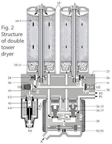
(19a-Pressure Storage Tanks for Regeneration Stage, 19b-Pressure Storage Tanks for Drying Stage, 19.7-Desiccant, 19.11-Oil Separator Cylinder with Lassie Ring, 24- Check Valve, 25-Bracket, 34-Double Piston Valve, 34.15、34.17-K Ring, 43-Solenoid Valve, 50-Regeneration Tank Nozzle (Regeneration Hole), 55-Pilot Valve, 56、70-K Ring, 71-Relief Valve, 92-Insulation Sleeve, P1-Air Inlet in front of the Compressor, P2-Discharge Air Inlet to Main Air Cylinder, A-Air/Condensate, O1、O2、O3-Air Vent Hole, V1~V10-Valve Seat)
The twin-tank type cooling-regeneration adsorption and drying plant can run two processes at the same time, namely the drying stage and the regeneration stage. When the desiccant in one storage tank is regenerated, the main gas stream in the other storage tank will be dried.
In Fig. 2 the pressure storage tank (19b) is in the drying phase and the pressure storage tank (19a) is in the regeneration phase. The cycle control device controls the solenoid valve body (43) to be energized and the valve seat V3 opens. The compressed air stream coming out of the compressed air connection P2, after shunting, flows through the open valve seats V2 and V3 to the piston valve (34). Open seats V6 and V7 by pressing the piston against the spring, with the force to the lower or upper position. The flow of compressed air supplied by the compressor and subsequently subjected to re-cooling and pre-drainage arrives at the air cylinder (19b) via connection P1 and the open valve seat V7. It flows upwards from below and then downwards through the center tube, through the check valve (24b) and the relief valve (71) and is directed to the connection P2. Before flowing into the desiccant (19.7), the air flows through the Rasi ring in the oil separator (19.11) for priming.
After many cycles of circulation, vortexing and collisions, the smallest droplets of oil and water remaining in the compressed air falls on the relatively large surface of the Rasi ring. It then forms relatively large droplets which fall by gravity into the collector chamber below. Then, when passing through the desiccant, the moisture still present in the air is sucked out, allowing the compressed air to flow out of the pressure storage tank (19b) with a relative humidity of less than 35%. A portion of the dried air is diverted, depressurized through the regeneration tank nozzle (50) and then sent in the opposite direction after passing through the desiccant in the pressure storage tank (19a). This depressurized air, also known as regeneration air, draws moisture from the desiccant to be regenerated and is discharged into the atmosphere through the open valve seat V6 and the muffler. When the valve solenoid (43) is de-energized, seat V3 closes and V4 opens. The control line to the piston valve (34) is exhausted. The pressure reservoir (19a) undergoes the drying stage and the pressure reservoir (19b) undergoes the regeneration stage.
5. Rectification and Validation: Air Compressor Lubricant
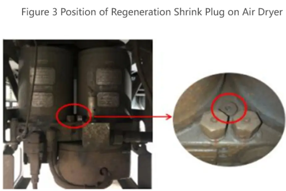
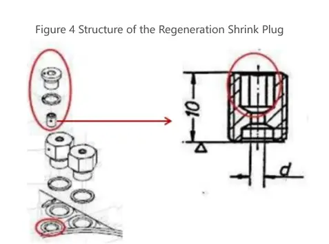
The air dryer’s regeneration shrink plug is mounted on the back side of the air dryer’s status indicator (shown in red circle in Figure 3). The regeneration plug is fitted into the air dryer housing and sealed by means of a screw plug and a sealing ring. The structure of the regeneration shrink plug is shown in Figure 4, which is an external thread of M8x1mm, with a small hole of diameter d at the inner end, namely the regeneration hole, and the regeneration shrink plug hole (regeneration hole) of the drying tower of the city metro is 1.2mm in diameter.
5.1 First Trial Rectification
After changing the regeneration hole diameter of K051 and 6 cars to 2.3mm, the sampling data of compressor operation rate is shown in Table 2, and the average operation rate is about 40%~50%.
| Table 2 Record of the Operating Rate of the First Trial Rectification | |||||
| Dates | Running Time of Air Compressor/min | Running Time of the Day on the Main Line/min | Air Compressor Operating Rate | ||
| Tc1 | Tc2 | Tc1 | Tc2 | ||
| 2019.8.19 | 564 | 0 | 1168 | 48.29% | / |
| 2019.8.20 | 0 | 444 | 1039 | / | 42.73% |
| 2019.8.21 | 540 | 0 | 1147 | 47.08% | / |
| 2019.8.22 | 0 | 444 | 1041 | / | 42.65% |
| 2019.8.25 | 540 | 0 | 1143 | 47.24% | / |
| 2019.8.27 | 558 | 0 | 1168 | 47.77% | / |
| 2019.8.30 | 0 | 456 | 1058 | / | 43.10% |
| Average Operating Rate | 47.60% | 42.83% | |||
The air compressor’s capacity to beat the wind is tested as follows:
- (1) A single air compressor in the warehouse is used to beat the wind: the total wind pressure rises from 750Kpa to 900Kpa, and the time taken increases from 90 seconds to 180 seconds.
- (2) One of the total air cylinder cut-off valves was opened to the cut-off position, and the total air pressure remained stable at 850kpa and could not be increased to 900kpa.
- (3) Positive line test, truncate a car bogie truncation plug door, with ATP mode, stations stop for testing, unilateral operation wind pressure maintains at 790Kpa stable.
5.2 Second Trial Rectification
After changing the diameter of regeneration holes of K111 and 6 cars to 1.8mm, the operation rate of the air compressor does not meet the requirement of the minimum operation rate, and the sampling data is shown in Table 3.
| Table 3 Record of the Operating Rate of the Second Trial Rectification | |||||
| Dates | Running Time of Air Compressor/min | Running Time of the Day on the Main Line/min | Air Compressor Operating Rate | ||
| Tc1 | Tc2 | Tc1 | Tc2 | ||
| 2019.11.02 | 0 | 312 | 1078 | / | 28.94% |
| 2019.11.03 | 300 | 0 | 980 | 30.61% | / |
| 2019.11.13 | 324 | 0 | 1090 | 29.72% | / |
| 2019.11.17 | 324 | 0 | 1076 | 30.11% | / |
| Average Operating Rate | 30.14% | 28.94% | |||
5.3 Third Trial Rectification
After changing the regeneration hole diameter of car K021 and car K106 to 2.0mm, the sampling data of Air Compressor Lubricant operation rate of car K106 is shown in Table 4, and the average operation rate is 34.44%. car K02 captures only one set of valid data, and the operation rate is 30.51%.
| Table 4 Record of the Operating Rate of the Third Trial Rectification | |||
| Dates | Running Time of Air Compressor/min | Running Time of the Day on the Main Line/min | Air Compressor Operating Rate |
| 2020.1.10 | 6.7 | 1116 | 34.66% |
| 2020.1.12 | 6.4 | 1099 | 34.94% |
| 2020.1.14 | 6.6 | 1135 | 34.89% |
| 2020.1.18 | 5.6 | 958 | 35.07% |
| 2020.1.20 | 6.4 | 1123 | 34.19% |
| 2020.1.22 | 6.2 | 1131 | 32.89% |
| Average Operating Rate | 34.44% | ||
After the rectification, the operation rate roughly meets the requirements, and to avoid a drop in the operation frequency, we carry out a fourth trial rectification.
5.4 Fourth Trial Rectification
After changing the regeneration hole diameter of K101 and 6 cars to 2.1mm, the sampling data of compressor operation rate is shown in Table 5.
| Table 5 Record of the Operating Rate of the Fourth Trial Rectification | |||||
| Dates | Running Time of Air Compressor/min | Running Time of the Day on the Main Line/min | Air Compressor Operating Rate | ||
| Tc1 | Tc2 | Tc1 | Tc2 | ||
| 2020.6.20 | 0 | 420 | 1080 | / | 38.89% |
| 2020.6.21 | 300 | 0 | 950 | 31.58% | / |
| 2020.6.22 | 0 | 444 | 1110 | / | 40.00% |
| 2020.6.24 | 0 | 450 | 1110 | / | 40.50% |
| 2020.6.25 | 342 | 0 | 1060 | 32.26% | / |
| 2020.6.26 | 0 | 438 | 1065 | / | 41.13% |
| 2020.6.27 | 342 | 0 | 1050 | 32.57% | / |
| 2020.6.30 | 0 | 456 | 1120 | / | 40.71% |
| 2020.7.1 | 366 | 0 | 1090 | 33.58% | / |
| Average Operating Rate | 32.45% | 40.14% | |||
The air compressor’s capacity to beat the wind is tested as follows:
- (1) A single air compressor in the library beats the wind: the total wind pressure rises from 750Kpa to 900Kpa, taking about 3 minutes.
- (2) One of the total air cylinder cutoff plug gates is opened to the cutoff position in the bank, and the total air pressure can be maintained at 900kpa.
- (3) Cut off one master cylinder plug door and simulate the mainline test (fast braking every 2 minutes), the train’s total wind pressure increased from 600Kpa to 860Kpa stable in about 5 minutes and 20 seconds.
After the test, after the diameter of the regeneration hole of the air compressor double tower dryer is changed from 1.2mm to 2.1mm, the operation rate of the Air Compressor Lubricant meets the requirement of the minimum operation rate, and there is no emulsification of lubricating oil of the air compressor, and the air pumping capacity meets the operation requirement of the main line.
6. Conclusion
There are many reasons for the emulsification of air compressor lubricating oil, serious emulsification of the lubricating oil will make the lubrication of the compressor’s rotor and bearings will not achieve the desired effect, which leads to Air Compressor Lubricant failures such as increased load, rotor jamming, abnormal noise, etc., which in turn leads to motor and compressor burnout, etc., and seriously affects the safe operation of the train. After experiencing relatively minor emulsification in a city’s subway, to avoid frequent lubricant changes and damage to the equipment, we performed a targeted rectification in order to improve the compressor’s operating rate. The regeneration shrinkage hole φ of the twin-tower dryer of the air source system was changed from 1.2mm to 2.1mm, and after two years of operation, there was no emulsification of air compressor oil in the subway, which effectively guaranteed the safety of train service.
In the future design and manufacturing phase of the new line and new cars, when the braking system match selection of air source products, we should fully consider the actual situation, and conduct air consumption calculations and experimental verification, and select the appropriate displacement of the air source device, and reduce the probability of the occurrence of the air compressor lubricant.


