The level of energy consumption is a comprehensive reflection of a country’s economic structure, mode of growth, level of science and technology, management capacity, consumption pattern and national quality. Therefore, energy conservation is necessary in the light of the realization of sustainable development of the national economy. Practice has proved that in the compressor and other general-purpose machinery drive motor, if using frequency conversion speed control, you can achieve a considerable effect – energy will save 15% to 40% or more. However, due to various constraints, the current use of Mobile Frequency Conversion drive on the compressor is less than 10%, and in the mobile screw air compressor using frequency converter is almost less than 1%.
1. Difference between Traditional Control and Frequency Conversion Control of Screw Air Compressor
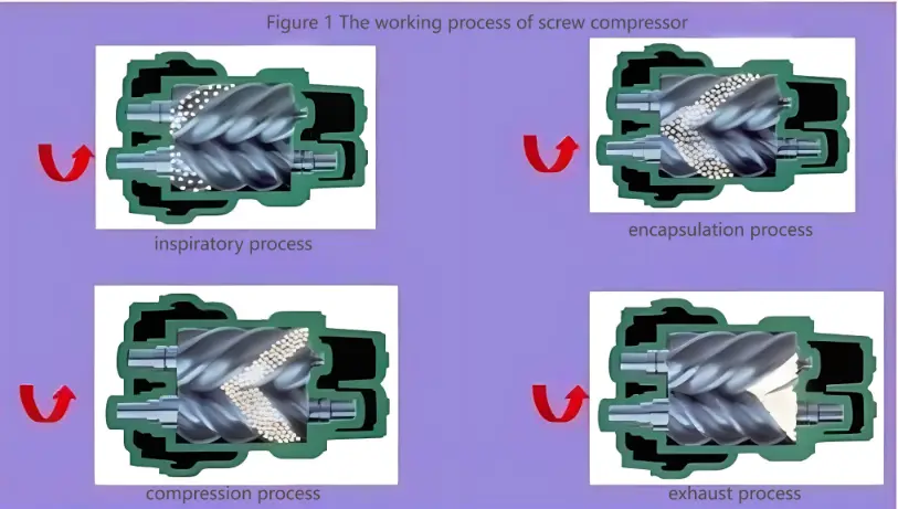
1.1 The Working Process of Screw Air Compressor
(1) Suction Process
When the rotor is rotating, the space of the tooth groove of the main rotor and the vice-rotor is maximized when it is turned to the opening of the inlet end wall, in this case, the groove space of the rotor is connected to the free air of the air inlet, and the air in the grooves is completely discharged during exhaust. At the end of the exhaust, the tooth groove is in a vacuum state, and when it turns to the air inlet, the outside air is sucked in and flows into the tooth groove of the main rotor and the vice rotor in the axial direction. When the air fills the entire tooth groove, the inlet side face of the rotor turns away from the air inlet of the housing, and the air between the tooth grooves is immediately closed.
(2) Containment and Conveying Process
When the main and vice two rotors are in the end of suction, the main and vice rotor tooth summit and casing closed, this time the air in the tooth groove closed and no longer outflow, this is the “closed process”. The two rotors continue to rotate, the tooth peaks and grooves in the suction side coincide, the coincidence surface gradually move to the exhaust side.
(3) Compression and Injection Process
In the process of transportation, the meshing surface gradually move to the exhaust side, that is, the meshing surface and the exhaust port of the teeth between the groove is gradually reduced. The gas in the groove is gradually compressed, the pressure increases, this is the “compression process”. At the same time in the compression, the lubricating oil is also due to the pressure difference and sprayed into the compression chamber and chamber gas mixing.
(4) Exhaust Process
When the engaging end of the rotor is turned to communicate with the casing exhaust, (This is when the compressed gas has the highest pressure) The compressed gas begins to be discharged, until the tooth peak and tooth groove of the joint surface moved to the exhaust end surface, at this time the two rotor meshing surface and the casing of the exhaust port of the tooth groove space is zero.
1.2 Conventional Electric Control Principle of Screw Compressor
Usually, rotary screw compressor users always select the volumetric flow rate of the compressor according to the maximum working conditions of air consumption. However, in the course of use, there will always be a requirement to change the volumetric flow rate of the compressor for various reasons in order to adapt to the actual operating conditions. In addition, it can be seen from the principle of operation, belonging to the volume of the volumetric screw compressor volumetric flow rate, not due to the increase in the back pressure and its own reduction. Therefore, if you do not do the corresponding effective regulation, it not only increases the power consumption, in some cases, it may also occur accidents. Therefore, it is necessary to set up the regulating and control mechanism to regulate the volume flow rate.
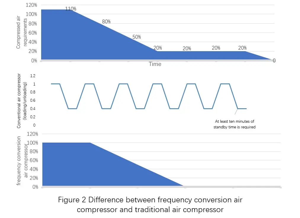
At present, the traditional mobile screw air compressor adopts two-point control (upper and lower limit control) or start-stop control (small machine). That is, when the pressure of compressed air in the cylinder reaches the upper limit of the set value, the air compressor through its own air pressure or oil pressure to close the inlet valve, small air compressor will shut down. When the pressure drops to the lower limit of the set value, the air compressor opens the inlet valve, and the small air compressor will start again. Traditional control methods are prone to impact on the power grid and damage to the compressor itself, especially when the air consumption fluctuates frequently.
Take two-point control as an example, under normal working condition, air is compressed into the storage tank. Air compressor points of detection (including compressed air temperature, pressure, screw temperature, cooling water pressure, temperature and oil pressure, oil temperature, etc.) and overall control is controlled by the host. When the outlet pressure of the air compressor reaches the upper limit of the set value, the air inlet is closed through the hydraulic manifold valve, and at the same time, the internal circulation line is opened for self-circulation operation. At this time, the air-using units continue to use air. When the outlet pressure drops to the lower limit of the set value, the hydraulic manifold valve closes the circulating pipeline, opens the air inlet, and the air is compressed by the filter into the storage tank.
1.3 the Control Principle of Frequency Conversion Screw Air Compressor
According to the mechanical structure, the volumetric flow rate of the screw compressor is directly proportional to the rotational speed. Therefore, by changing the rotational speed of the compressor, the purpose of regulating the volumetric flow rate can be achieved. The main advantage of this type of regulation is that the structure of the entire compressor unit does not need to make any changes, and in the regulation of the working conditions, the gas in the compressor process is basically the same. Therefore, changing the rotational speed is a very effective adjustment method.
It is based on the principle of speed regulation, frequency conversion air compressor began to appear on the market. It automatically changes the rotating speed of the main engine according to the size of gas consumption and maintains a stable system pressure. When the air consumption of the system is reduced, the amount of compressed air provided by the compressor will be greater than the system consumption, the inverter compressor will reduce the speed, and output the amount of compressed air, to maintain a stable system pressure value. If when the system consumption of air increases, the amount of compressed air the compressor provides will be less than the amount of system consumption, the speed of the inverter compressor will be relatively increased, and at the same time output the amount of compressed air, to maintain a stable system pressure value.
This type of operation allows the frequency conversion air compressor to directly and quickly reflect changes in system pressure and provide the change in air volume required for system consumption, which is shown in Figure 2.
2. Design of the Mobile Frequency Conversion Air Compressor
2.1 Permanent Magnet Motor Direct Drive System
In order to maximize reliability and reduce cycle time costs, a mobile frequency conversion air compressor needs to be small enough for the space, large enough for the air output and low enough for the energy consumption. Unlike the traditional retrofit of screw air compressors, mobile compressors have to take into account the size and output due to space constraints. Although in conventional designs, gearboxes are used for reduction control and torque increase, permanent magnet motors (PM motors) are now used for direct drive of the compressor screw (as shown in Figure 3).
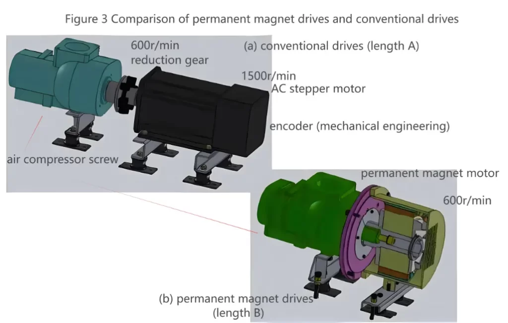
In the usual compressor drive, the synchronous speed of the gear motor is usually at 1500r/min, and then by selecting the appropriate gear ratio, we can obtain the appropriate screw running speed. In direct drive systems, the rated speed of permanent magnet motors is usually in the range of 300 r/min to 600 r/min. The stator windings of a permanent magnet motor are basically the same as those of an asynchronous motor, but it is capable of higher current loads than an asynchronous machine.
As it can be seen from Figure 3, for the mobile compressor, the space occupied by the permanent magnet motor is reduced from length A to length B. As a result, the user will benefit from the direct drive, which has at least the following advantages: the use of a lower number of mechanical drive components, which will enable the plant to save engineering and construction costs and installation costs; the direct use of synchronous motors reduces torque pulsations and ensures better reliability of compressor operation; less mechanical transmission components make the equipment has higher reliability; using less parts makes the system more simple, and greatly reduces maintenance costs.
2.2 PID Programming
In addition to the direct drive design, the mobile frequency conversion air compressor design should also meet the following requirements:
- (a) The stabilized pressure fluctuation range of the outlet pressure of the gas storage tank maintained under the motor frequency conversion operation state cannot exceed ±0.02MPa.
- (b) The system has both open-loop and closed-loop control loops.
- (c) In the case of a small amount of electricity and gas, the frequency converter is in low-frequency operation, you should ensure that the temperature of the motor winding and motor noise does not exceed the permissible range.
According to the above principle,a scheme can be given as shown in Figure 4.In this scheme,the pressure closed-loop control system consisting of frequency converter,pressure transmitter,motor,compressor and PID controller can automatically adjust the motor speed, stabilize the air pressure in the storage tank within the set range and perform constant pressure control. Feedback pressure and set pressure through the PID controller or inverter built-in PID to compare the operation and real-time control of the output frequency of the inverter, so as to adjust the motor speed, so that the air pressure in the tank is stabilized at the set pressure.

3. Conclusion
According to the principle of direct drive and PID control, a mobile screw compressor experimental equipment can be designed (as shown in the figure below).
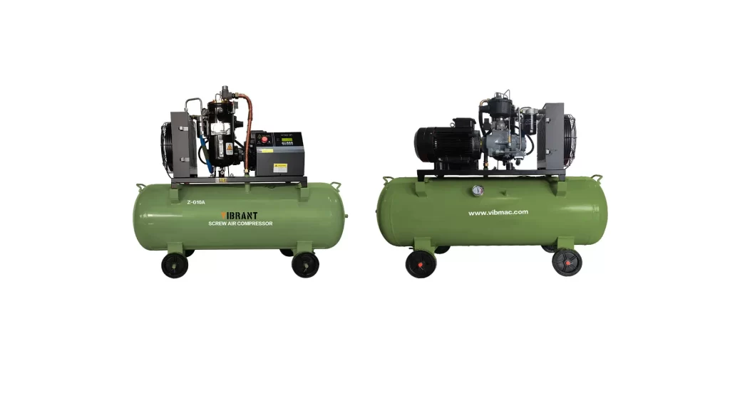
After relevant tests, the device already has the following advantages:
- (1) Stable air pressure: As the frequency conversion air compressor utilizes the stepless speed regulation feature of the frequency converter. By means of the controller or the inverter’s internal PID regulator, the pressure can be quickly adjusted and controlled. The air pressure stability is exponentially improved compared to the upper and lower limit switching controls of industrial frequency operation.
- (2) More energy-saving: Although the screw compressors of various manufacturers have adopted different energy-saving operation modes. However, due to the frequency converter (this system is using Hitachi inverter) is based on the actual air consumption of real-time adjustment of the motor speed, low air consumption when the air compressor will automatically hibernate, which greatly reduces the loss of energy.
- (3) Start without impact: because the inverter itself is a soft start device, the highest starting current is about twice the rated current. The starting shock is very small compared to the general 6 to 7 times the rated current of the industrial frequency starting. Because it is a mobile compressor, this shock will greatly reduce the capacity and stability requirements of the generator system, as well as greatly reduce the shock to the overall mechanical system.
In conclusion, for greater reliability and lower run cycle costs, a mobile inverter screw air compressor should fulfill the requirements of small enough space, large enough air output and low enough energy consumption. The use of permanent magnet motors for direct drive of air compressor screws can greatly reduce the size and ensure that the motor speed and torque meet the design requirements; through the controller or inverter internal PID regulator, the air compressor can achieve rapid adjustment and control of the output pressure, minimizing energy consumption. READ.


