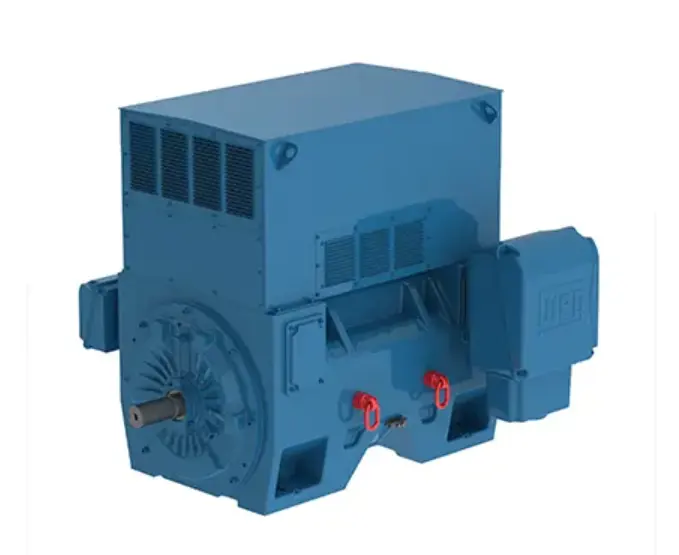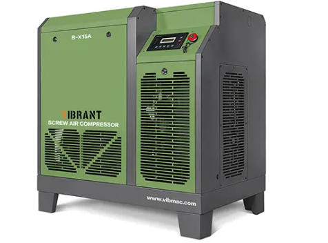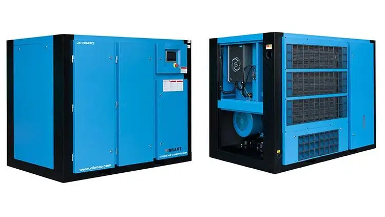
In a Non-ferrous Smelter project, compressed air is used for equipment and instrumentation control as well as raw material delivery, so an air compressor station was set up in the plant. Combined with the design and production practice of this compressor station, our company discusses and analyzes the relevant parameters and main control factors in the design.
1. Calculation of Compressed Non-ferrous Smelter Air Consumption
The compressed air consumption needs to meet the total amount of air used for the production of the project, and the information for calculating the compressed air load should be included:
- Name, specifications and quantity of gas-using equipment;
- Maximum and average hourly gas consumption of the equipment; gas supply pressure requirements (maximum and minimum pressure of the gas-using equipment);
- Quality requirements of compressed air, such as oil content, dust content, water content, etc.;
- Users' requirements for reliability of gas supply, continuity of gas supply, etc;
- The development plan of the factory, the location of the air compressor reserved.
Compressed air in non-ferrous smelters has more points of use, of which the continuous and intermittent points of use have a greater impact on the load, the compressed air requirements of the design project are also characterized in this way, details of which are given in Table 1.
| Table 1 Summary of Compressed Air Requirements | ||||
| Gas Point Sub-code | Nominal Gas Consumption(m³/min) | Point-of-Use Pressure(Mpa) | Characteristics of Gas Consumption | Use |
| 103 | 10 | -0.6 | Intermittent, No Oil Gas | Fine Filter Blowback, Average 5 |
| 104 | 5 | -0.6 | Continuous, No Oil Gas | Degreasing |
| 105 | 100 | -0.6 | Intermittent, No Oil Gas | Filter Press Backblow, Average 60 |
| 106 | 10 | -0.6 | Intermittent, No Oil Gas | Filter Press Blowdown, Average 5 |
| 102 | 30 | -0.6 | Intermittent, Regular Gas | Filter Press Blowdown, Average 15 |
| 105 | 150 | -0.6 | Continuous, Regular Gas | Air Supply for Pneumatic Diaphragm Pumps |
| 109 | 20 | -0.6 | Intermittent, Regular Gas | Fine Filter Blowback, Average 10 |
| 112 | 10 | -0.6 | Intermittent, Regular Gas | Filter Press Blowdown, Average 5 |
| Instrument Gas | 20 | 0.8 | Continuous, Instrument Gas | Various Instrumentation |
| Note: The quality of oil-free gas and instrument gas in the table requires the oil content to be less than or equal to 1ppm and the dust content to be less than or equal to 1mg/m³. | ||||
At present, there are many ways to calculate the compressed air consumption, so you should understand the different points of use of the law, you can refer to the following kinds:
(1)Q1: Designed consumption based on maximum consumption.
Q1 = ΣQmaxK1K2(1+ψ1+ψ2+ψ3) (1)
In the above formula: Q1 is the design of compressed air consumption, the unit is m3/min; ΣQmax is the sum of the maximum gas consumption of each gas point at the same moment, in M3/min; K1 is the coefficient of simultaneous use of compressed air, which is related to the number of air points and the pattern of air use. When a single point of use is 1.0, the number of points of use increases and the value of k decreases; k2 is the plateau correction factor, as shown in Table 2. Ψ1 is the leakage coefficient of the piping system, which is shown in Table 3; Ψ2 is the wear and tear coefficient of wind-powered tools, with a size ranging from 0.15 to 0.20; and Ψ3 is the consumption coefficient which is not foreseen in the design, with a value of 0.1.
(2) Q2:Designed consumption based on theoretical average consumption.
Q2 = ΣQ0K1K2(1+ψ1+ψ2+ψ3) (2)
In the above formula: ΣQ0 indicates the theoretical average gas consumption sum of each gas point, the unit is m3/min; the significance of other symbols is the same as described in formula (1).
(3) Q3:Designed consumption based on maximum consumption and theoretical average consumption.
Q3 = K1K2(ΣQmax+ΣQ0’)(1+ψ1+ψ2+ψ3) (3)
In the above formula: ΣQmax represents the sum of the maximum gas consumption at the same moment at each major gas consumption point, the unit is m3/min. ΣQ0’ denotes the sum of theoretical average gas consumption of the remaining gas-using points in m3/min; the significance of other symbols is the same as that of formula (1) and formula (2).
(4) Q4:Designed consumption for continuous load.
Q4 = ΣQ(1+ψ1+ψ3) (4)
In the above formula: ΣQ indicates the compressed air consumption of the point of continuous work, the unit is m3/min; other symbols have the same meaning as the formula (3).
According to the project's characteristics of the use of compressed air, use formula (2) to calculate the compressed air consumption, combined with the specific circumstances of the project, K1 takes the value of 0.95, K2 takes the value of 1.0, Ψ1 takes the value of 0.15, Ψ2 takes the value of 0, Ψ3 takes the value of 0.1, we can get the total gas consumption of oil-free gas as well as instrumented gas shown in the formula (5), and the formula of the total consumption of common gas (Ψ2 takes the value of 0.15) is shown in the formula (6).
Q2 = (5+5+60+5+20)×0.95×1×(1+0.15+0+0.1)≈113(m3/min) (5)
Q2=(15+150+10+5) ×0.95×1×(1+0.15+0.15+0.1)≈240(m3/min) (6)
| Table 2 Plateau Correction Factors (Calculated Values) | ||
| Altitude(m) | K2 | |
| At 20°C | At 0°C | |
| 0 | 1 | 1 |
| 300 | 1.035 | 1.038 |
| 600 | 1.072 | 1.078 |
| 900 | 1.11 | 1.119 |
| 1200 | 1.15 | 1.162 |
| 1500 | 1.191 | 1.207 |
| 1800 | 1.233 | 1.254 |
| 2100 | 1.278 | 1.303 |
| 2400 | 1.324 | 1.353 |
| 2700 | 1.372 | 1.406 |
| 3000 | 1.422 | 1.462 |
| Table 3 Leakage Coefficients for Piping Systems Ψ1 | |
| Total Length of Pipeline (km) | Ψ1 |
| <1 | 0.1 |
| 1~2 | 0.15 |
| >2 | 0.2 |
2. Non-ferrous Smelter Air Compressor and Unit Selection
Commonly used air compressors are screw, piston, diaphragm and centrifugal (turbine). According to the working principle it can be categorized into volumetric type and speed type; according to the structure form it can be categorized into reciprocating type, rotary type and centrifugal type. Table 4 is the classification of commonly used air compressors and the main advantages and disadvantages of the comparison.
| Table 4 Classification of Commonly Used Air Compressors and their Main Advantages and Disadvantages | |||||
| Advantages, Disadvantages and Applications | Volumetric Air Compressor | Speed Compressor | |||
| Reciprocating | Rotary | Centrifugal (Turbine) | |||
| Piston Type | Membrane Type | Sliding Vane Type | Screw Type | ||
| Advantages | Stable back pressure, a wide range of pressure; high thermal efficiency; in the general pressure range, low material requirements, mostly made of ordinary steel | Simple, compact and lightweight structure; easy to use, operate and maintain; less overhauling and long service life | Small dimensions, light weight; uniform air supply, low vibration; fewer wearing parts, high operating rate, easy to realize automatic speed regulation | ||
| Disadvantages | The rotational speed is not high, the structure is complicated, there are many wearing parts, and the maintenance quantity is large; there is vibration when running; the air transmission is not continuous, and the air pressure has pulsation | More difficult to seal and less efficient | High cooling water consumption | ||
| Applications | Suitable for high pressures, small and medium flow rates | Suitable for low pressure, small and medium flow rates | 120~1500m³/min, pressure below 2.5MPa | ||
According to the compressed air consumption and use characteristics, and combined with the specifications of air compressor models, the final equipment allocation of this project is shown in Table 5.
| Table 5 Air compressor and After-treatment Equipment Configuration List | ||||
| Air Supply System | Equipment Name and Specification | Supply Pressure | Quantity | Specification of After-treatment Equipment |
| Oil-free Gas and Instrument Gas System | Oil-free Screw Air Compressor Q = 72m³/min | 0.8 | 2 | Microthermal Adsorption Dryer A90, 2 sets Coarse Filter SAGL-80FC, 2 sets |
| General Gas System | Screw Air Compressor Q = 91m³/min | 0.8 | 1 | Fine Filter SAGX-80, 2 sets Refrigerated Dryer Q = 100m³/min, 1 set Oil-water Separator SAYF-100, 1 set |
| Screw Air Compressor Q = 65m³/min | 0.8 | 3 | Refrigerated Dryer Q = 75m³/min, 3 sets Oil-water Separator SAYF-80, 3 sets | |
3. Selection of Compressed Air Storage Tanks
Properly configured storage tanks can stabilize the pressure in the compressed air piping system, which is conducive to better separation of moisture and impurities in the compressed air. A safety valve must be provided on the gas storage tank, and a shut-off valve should be provided between the tank and the gas supply pipeline. The selection of gas storage tanks can refer to formula (5).
Vc = KV (5)
In the above formula: Vc is the volume of the storage tank, the unit is m3; V is the exhaust volume of the air compressor, the unit is m3/min; K is the empirical coefficient, which can be selected from Table 6.
| Table 6 Empirical Coefficients for Choosing Gas Storage Tanks k | |||
| Gas Storage Tank | Air Compressor Exhaust Volume (m³/min) | ||
| K | <6 | 6~30 | >30 |
| 0.2 | 0.15 | 0.1 | |
4. Process Configuration Principles
Principles of Non-ferrous Smelter air compressor station configuration:
- The air compressor station is generally constructed separately in the plant and consists of an air compressor room and an auxiliary equipment room.
- The location of the air compressor station should be chosen in a place with clean air and good ventilation. It must be kept at a certain distance from places and chimneys that are prone to generate dust and often emit corrosive gases, etc., and it is better to be located above the dominant wind direction.
- Gas storage tanks should be placed outdoors, in principle, they need to be located in the shaded side of the building, and the direction of compressed air usage should be taken into account in the specific project. In order not to affect the principle of lighting and ventilation, the net distance between the vertical storage tank and the external wall of the air compressor room should usually be more than 1m.
- The air compressor with the same type in the compressor station can be arranged next to each other for easy management; the air compressors should be arranged in a single row, and when the number of units is more than 6, a double-row arrangement can be considered; a passageway of at least approximately 1.5 m wide should be maintained between each air compressor, and the outer edges of the air compressors, should be at least 1.0 m greater than the distance between the walls and columns.
- Air compressor units emit a certain amount of heat during operation, so if you can take advantage of natural ventilation conditions, you can try to avoid the station temperature increasing.
- A drainage gutter should be provided in the compressed air station and wooden boards should be covered well.
- The compressed air station is one of the noise sources in the factory, which needs to be treated by adding a cover to the compressor body, installing silencers or anti-surge regulating valves on the pipelines, and installing sound-absorbing perforated boards or mineral wool sound-absorbing boards on the walls inside the building. Places or buildings with noise protection requirements around the compressed air station need to maintain a certain distance according to the standards. The air compressor room is noisy and has a high temperature, so it is necessary to take sound insulation treatment in the duty room.
5. Conclusion
The compressed air in the nonferrous smelter is mainly used for pneumatic equipment and instrument remote control, solution mixing, powder material conveying and other important processes. The air compressor station provides a stable compressed air source for the production and operation of the nonferrous smelting plant. The core of the design of the air compressor station is to correctly calculate the compressed air consumption, and grasp the fluctuation range of air consumption, in order to reasonably select the type of air compressor equipment. The process arrangement of the compressor station, in addition to meeting its specific requirements, should also satisfy the appropriate distance between the various points of use, as well as the economy of pipeline routing. In addition, the design of the compressor station should also facilitate on-site production management as well as daily inspection and maintenance of the equipment.
Our company discusses and analyzes the characteristics and main control factors of PM VSD screw air compressor design in combination with the application practice of air compressor station. With the goal of maximizing the service life of compressor station equipment, reducing the amount of maintenance and inspection work, and comforting the staff on duty, our company adheres to the principle of designing from the source and focusing on the details to actively ensure that the compressor station operates stably in a safe environment.


