Numerical Calculation of Air Compressor Motor Performance and Loss Research
2024-02-28
Air compressor is a kind of equipment used to compress gas, its motor has induction motor, brushless DC motor, high speed permanent magnet motor, etc., and the utilization rate of high-speed permanent magnet motor is better than that of high-speed induction motor, so the research on permanent magnet motor is more extensive. Bailey C et al. describe the application of a high-speed permanent magnet motor with 8mW power and 15,000 rpm speed for compressors in the petrochemical industry. The stator of this motor is made of low-loss silicon steel sheets, and the rotor bearings are made of active magnetic bearings and rolling bearings, and two different types of bearings are compared separately using the principle of rotor dynamics. Soong et al. performed the electromagnetic and mechanical design of a high-speed, high-efficiency induction motor for centrifugal compressors and compared the electromagnetic characteristics, losses, and mechanical characteristics of three different types of motors (switched reluctance motor, permanent magnet synchronous motor, and induction motor). Jang SM et al. presented the design and analysis of a high-speed, high-power-density DC brushless motor with a 50kW, 70wrpm stage centrifugal compressor. The structural design criteria and power losses of high-speed motors are analyzed by theoretical analysis methods, and the results are verified by the finite element method.
For this air compressor with rated power of 10kW and rated speed of 100krpm, this paper designs and analyzes the motor applicable to it. First, the motor material should be selected, and the performance parameters and structural size parameters should be calculated, the performance curves of rotational speed and current, efficiency and torque should be analyzed to analyze the selected motor design parameters, and the stator and rotor losses of the motor should be analyzed by using finite element. Finally, by analyzing the rotor sheath material, and the stress of the surplus between the rotor and the sheath, to achieve the purpose of reducing the internal loss of the motor and improving the performance of the motor.
1. Materials and Methods
1.1 Selection of materials
Motor stator is an important part of the motor, which is mainly composed of three parts: stator core, stator winding and seat. It mainly produces a rotating magnetic field for the motor. In this paper, the stator material used is 0.2mm thick, special-purpose non-oriented electrical steel, type 20WTG1500. at 1.0T and 400Hz, the loss is less than 9.0W/kg and 15W/kg, respectively. saturated magnetic inductance is not less than 1.4T, and stacking coefficient is 92%.
1.2 Motor structure design
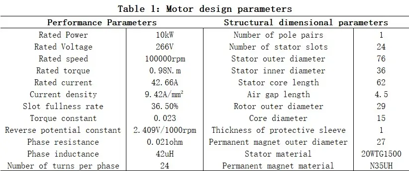
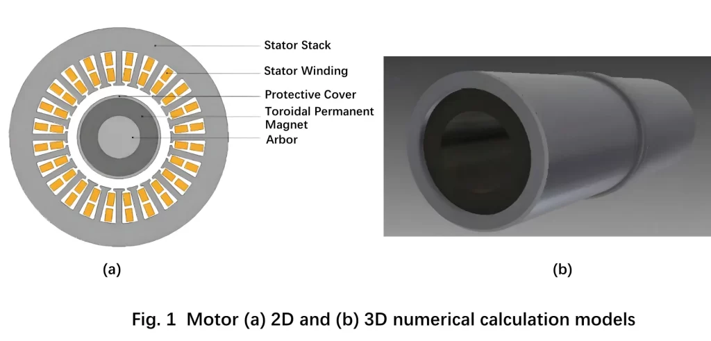
The stator winding structure adopts 24-slot structure, and the winding connection is double-layer short-pitch star connection with 24 turns per phase. In order to minimize the effect of skin effect, multiple strands per turn are wound in parallel.The rotor adopts a two-pole structure, the middle of the ring-shaped permanent magnet is a mandrel for transmitting torque, and the permanent magnet is connected by adhesive, in order to protect the permanent magnet from centrifugal force damage under high-speed rotation, the ring-shaped permanent magnet is externally set up with a protective sleeve, and the protective sleeve and the ring-shaped permanent magnet with an interference fit. Through the selection and calculation of the design parameters, the motor parameters that satisfy the above conditions are shown in Table 1.
1.3 Numerical calculation model of the motor
The 2D numerical computational model and 3D numerical computational model of the permanent magnet motor used for this air compressor are shown in Fig. 1.
2. Results and discussion: Air Compressor Motor
2.1 Motor Performance Analysis
With the model designed by the existing ideas, next we need to carry out the performance analysis of speed and current, efficiency and torque to verify whether it meets the design needs and safety requirements. As shown in Fig. 2, it can be seen from the graphs of speed and current, speed and efficiency, speed and torque that when the speed reaches 100000rpm, the current and torque are basically in line with the design parameters; and in 60000-100000rpm, the efficiency is above 80%, and in 100000rpm, the efficiency is above 90%.So by analyzing the performance of speed and current, efficiency and torque, this motor meets the design requirements in terms of performance.
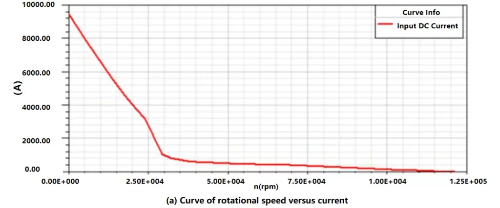
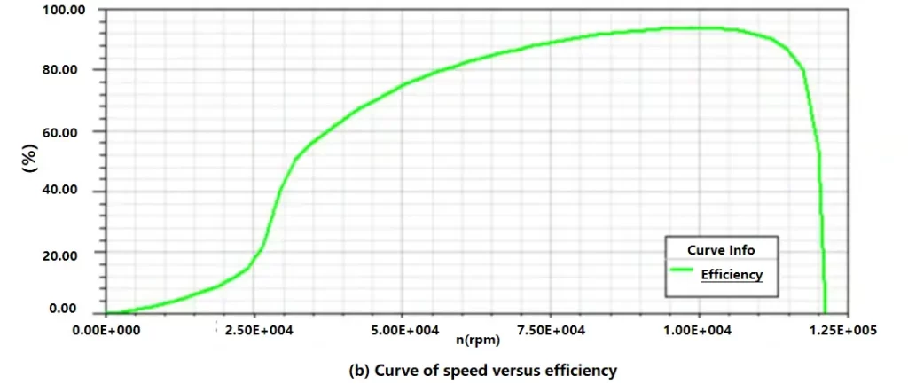
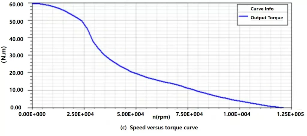
Fig. 2
2.2 Analysis of operating results under rated conditions
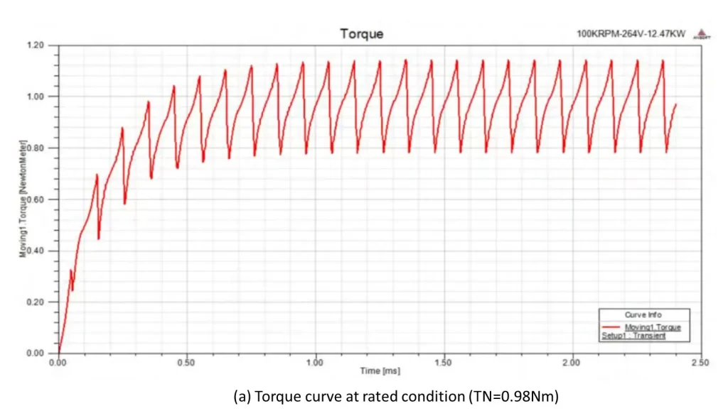
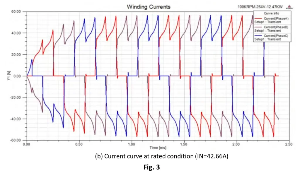
The specific operating conditions used in this simulation are voltage 250V and speed 99500rpm, and the torque and current curves under the rated condition obtained for this condition are analyzed. From Fig. 3, it can be learnt that: from the torque curve, the average value of torque is 0.98N.m under the rated condition, due to the small number of poles of the motor, the torque fluctuation is relatively large compared with the multi-pole motor, the fluctuation amplitude is 0.18N.m, accounting for 18.3% of the average value of the torque, considering that the rotor rotational moment of inertia is large, the period of the fluctuation of the torque is shorter, and the impact on the rotor speed can be neglected. The average value of current at rated condition is 42.66A as seen in the current curve. Through the current value, the current density can be found to be 9.42A/mm2. Since the stator is cooled by circulating water, the current density can be larger than that of an ordinary motor. Through the above average value of current and average value of torque, the torque constant of the motor can be found to be 0.023N/A.
2.3 Loss analysis of the motor
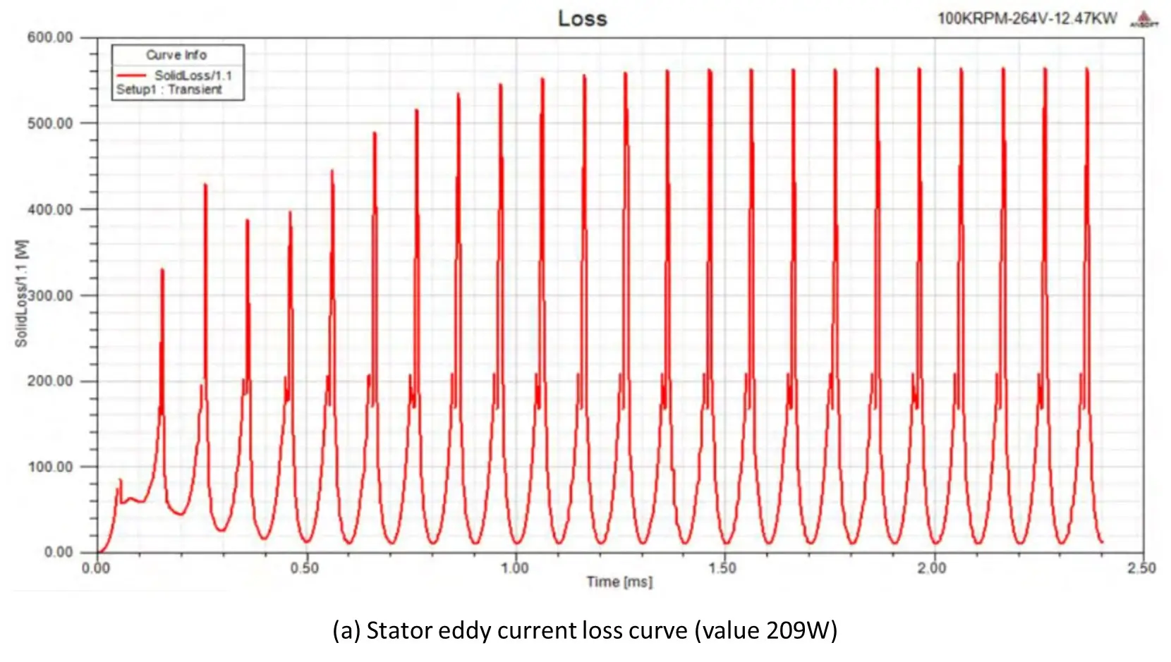
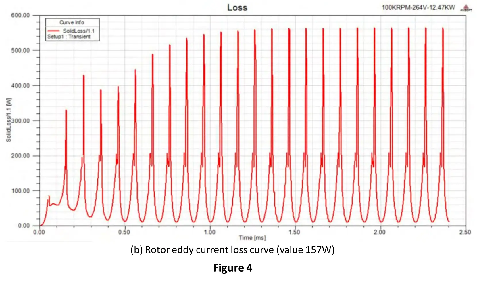
The loss analysis of the motor can be divided into stator loss and rotor loss, the specific experimental scheme analyses the stator loss at 266V, 100krpm rated operation and the rotor loss at 250V, 99500rpm rated operation. As shown in Fig. 4, the stator loss is mainly distributed in the combination of stator yoke and stator teeth, which is caused by the large magnetic density in this position; the value of stator loss is larger than that of rotor loss.
3. Conclusion
To improve the performance of the motor, this paper designs and analyzes a permanent magnet motor for an air compressor with a power of 10kW and a speed of 100krpm. For the design specifications of the motor, the motor material is selected, and the performance and dimensional parameters of the motor are calculated. The performance curves of speed versus current, efficiency and torque are used to analyze the selected design parameters of the motor and the stator and rotor losses of the motor are analyzed using finite elements. Finally, the effect of the range of interference on the safety factor of the motor is analyzed by analyzing the rotor sheath material, as well as the stress of the interference between the rotor and the sheath. The results of the study show that the stator with water circulation can have a current density that is on the high side compared to ordinary motors. At the same time, the protective sheath and mandrel edge loss is larger. Read more.


